For readers arriving via 3d ai maker, this article explains the difference between converting an STL to STEP and reverse engineering it, so you can choose the method that fits your CAD editing needs.
Converting an STL to STEP gives CAD software a solid it can measure and cut. It does not restore the sketches, cylinders, or fillets that made the original part. I use conversion when the mesh can stay as it is, and feature reconstruction when the design itself needs to change.
The short version
- Use SupaVoxel’s STL to STEP converter when you need a faceted solid for an assembly, a measurement, or a Boolean cut.
- The result is a real CAD solid, but its curved areas remain flat facets. It has no recovered sketches or feature history.
- Rebuild the part over the mesh when you need to change a hole diameter, adjust a fillet, or maintain dimensions for later revisions.
- Keep the original CAD file if you have it. Exporting a mesh and converting it back cannot restore the surfaces that were discarded.
“Editable CAD” can mean different things
Suppose a supplier sends you an STL of a bracket. You need to position it beside another part and subtract its shape from a block to check clearance. A faceted STEP solid can do that job: CAD software can treat it as a closed body rather than merely displaying a mesh.
Now suppose the hole needs a new diameter. In an original CAD model, that hole may be defined by a circle in a sketch and a cut feature. In the converted solid, its wall is a collection of flat faces. There is no diameter parameter to change. You might still add a new cut or build another feature against the body, but you are not editing the old hole as a hole.
That distinction matters more than the file extension. The STEP vs STL guide explains what each format stores: STEP can carry exact CAD surfaces, while STL stores triangles. Saving those triangles inside a STEP solid does not turn them back into the original surfaces.
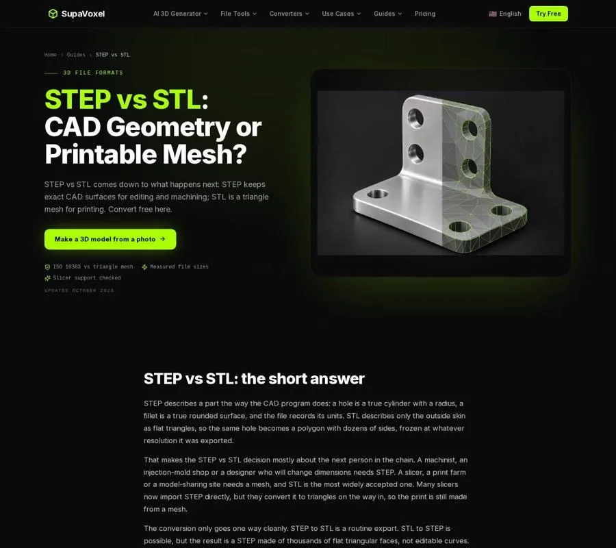
The format comparison helps separate an original CAD STEP file from a STEP solid constructed from an STL.
When the faceted solid is enough
The conversion route is useful when the existing shape is acceptable and your next operation does not depend on recovering its design intent. I would use it to place a supplied mesh in an assembly, take sections, check its overall size, or subtract it from another solid to form a cavity. It also gives me a body to reference while adding new CAD geometry.
Flat-sided parts are especially suitable. The converter merges neighboring triangles that lie on the same plane. In the page’s example, a cube with 12 STL triangles becomes a STEP solid with 6 faces. That makes its broad, flat surfaces much easier to work with than a separate CAD face for every triangle.
Curves are different. A cylinder with 64 sides remains faceted; merging flat regions cannot infer that its polygonal wall was intended to be one exact cylinder. The converter produces a closed, faceted STEP AP214 solid, not a parametric reconstruction.
That is still a practical result. If you only need the cylinder’s current shape as an assembly reference or the outline of a clearance cavity, rebuilding it may add work without improving the task. If you must specify its diameter or use its axis as a dependable design feature, the facets are a clue to remodel it—not a substitute for doing so.

The converter creates a solid with merged flat areas while leaving curved areas faceted.
When to reconstruct features instead
I rebuild when someone will need to revise the part by dimensions. Hole diameters, fillet radii, mating faces, and wall positions are easier to control when they come from constrained sketches and CAD features. A faceted reference can show where those features appear, but it cannot tell me what the designer intended their nominal dimensions to be.
A mesh is also an imperfect source for measurements on curves. An STL exporter has already chosen how closely triangles approximate each surface. A polygonal hole can suggest a diameter, but fitting a circle to those facets is an interpretation. If a drawing or a known mating part exists, I use it to establish the required dimension and use the mesh to check placement and overall form.
Reconstruction does not always mean remodeling every detail. For a mechanical part, I might recreate the mounting face and holes as clean CAD features while keeping an irregular outer shape as a reference. The decision is about which geometry must remain controllable. Decorative contours may only need to look right; a hole that locates a mating part needs a defined size and position.
Fusion’s Convert Mesh command has a Prismatic method that tries to fit planes and cylinders to mechanical meshes. It can be worth trying before a manual rebuild. I would still inspect the result against the design requirements rather than assume fitted features match the original intent.
A decision workflow for a mesh in CAD
- Name the change you need. “Put this shape in an assembly” points toward conversion. “Make the hole larger and keep it centered on the mounting face” points toward reconstruction. This question prevents a file-format change from being mistaken for a design change.
- Check whether the mesh describes a usable solid. Holes or open edges can leave an open shell instead of the closed body CAD operations expect. Repair those defects before converting. If the mesh is very dense, simplify it first; the converter’s guidance suggests 10,000 to 50,000 triangles as a more manageable range for CAD work.
- Check scale before trusting a measurement. STL has no unit field. The converter assumes millimeters unless you change File units, while the STEP it writes declares millimeters. Compare the size readout with a dimension you know before using the resulting solid to position or cut anything.
- Choose the least destructive route. If the shape itself needs no revision, convert it and try the intended assembly or Boolean operation. If critical dimensions must change, bring the mesh into CAD as a reference and create sketches and features for those areas.
- Validate the rebuilt geometry. Compare the new body with the mesh visually and check the dimensions that matter for its use. Where the mesh and a drawing disagree, decide which source governs the part before sending it on.
The STEP file from conversion and the STEP file from reconstruction may open in the same CAD program. Their difference becomes obvious at the next revision: one offers a faceted body you can work around; the other offers features you can deliberately change.
Deliver the right file after the edit
Once you have rebuilt the needed features, save the native CAD model for future changes and export STEP when another designer or a machine shop needs CAD geometry. Do not replace that editable source with an STL and expect to recover it later.
For printing, the destination is usually a mesh. SupaVoxel’s STEP to STL converter turns a .step or .stp part into a binary STL and shows its size in millimeters before download. That direction of conversion is straightforward because the CAD surfaces can be approximated with triangles. It is also a one-way loss of information: the STL no longer contains the exact cylinders and fillets.
If the CAD file contains several bodies, consider the print workflow before exporting. The converter writes them into one STL while retaining their positions. Export parts separately when you need separate print files.

After the CAD edits are complete, this converter makes an STL for a slicer.
Avoid the tempting shortcut
A converted solid can look reassuringly like the source model. That appearance does not prove it has sensible features underneath. Before handing it to someone else, describe it accurately as a faceted STEP solid if that is what it is.
I would not convert a dense sculpt merely to give it a STEP extension. Large face counts can make CAD work sluggish without making the shape more editable. Nor would I rebuild a part just to obtain a clearance reference when the existing mesh already answers the assembly question. Match the work to the next operation, not to a preferred file extension.
FAQ
Is a converted STL a real STEP solid?
Yes. The converter writes a closed STEP AP214 solid that CAD software can measure, section, cut, and combine. Its faces are planar facets, though, so it is not the original parametric design.
Can I change a hole after converting?
You can add CAD operations to the solid, but you cannot select the faceted hole and edit an original diameter parameter. For a controlled hole size, reconstruct that feature using a sketch and a cut.
Should I convert to STEP before printing?
No. Slicers use a mesh for printing, and converting an STL to STEP and back adds no useful geometry. Keep or export the STL for the slicer; use STEP when the next task calls for CAD work.