For readers exploring 3d ai maker workflows, this guide explains how to turn a grayscale heightmap into a solid STL relief using SupaVoxel, then prepare it for clear, support-free printing.
A heightmap turns brightness into height: light areas rise, dark areas stay low. I’ll show you how to prepare the image, control the shape of the relief, export a solid file, and print it so the contours are easy to see.
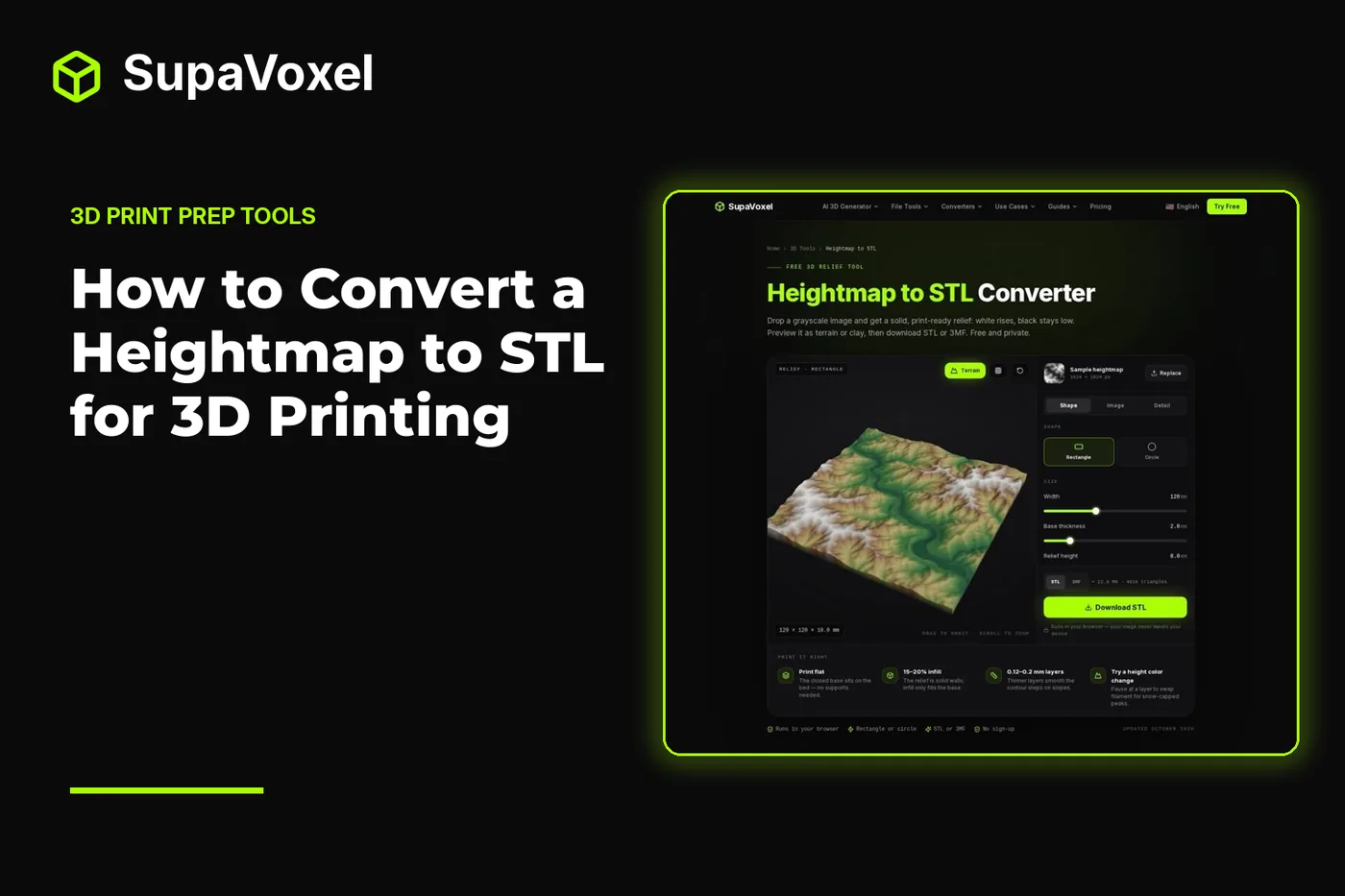
The short version
- Use a grayscale terrain export, depth map, or logo; white becomes high and black stays at the top of the base.
- In SupaVoxel’s heightmap to STL converter, choose a rectangle or circle, set the physical dimensions and relief, then adjust the image before exporting STL or 3MF.
- Start with the default base, relief, smoothing, and resolution settings. Change them to solve a visible problem, not just to make the file denser.
- Print the solid relief flat on its base without supports. Light the finished print from the side to make shallow slopes visible.
Start with an image that describes height
A heightmap is a grayscale image in which brightness has a specific meaning. Black marks the lowest point; white marks the highest; gray falls between them. That makes a terrain heightmap or a prepared depth map more predictable than an ordinary photograph. A bright patch in a photo might be sunlight rather than a raised surface, but the converter has no way to know that.
Look at the source image before uploading it. If the important ridges are barely distinguishable from the surrounding gray, they will also have little height separation unless you adjust contrast. If the source contains blocky compression marks, those marks may become small terraces. Clean edges and gradual tonal changes give you more control than trying to rescue a noisy image at export.
The browser tool accepts PNG, JPG, and WebP images up to 25 MB. You can also load its sample mountain heightmap to learn what the controls do before using your own file. Transparent pixels count as black, so an image with a transparent border will put that border at base level. Check that behavior deliberately if you are preparing a logo or an isolated patch of terrain.
Convert the image into a relief
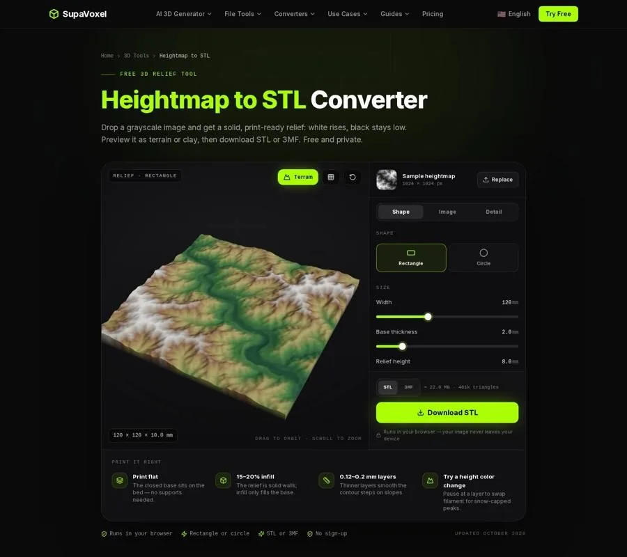
The Heightmap to STL page provides shape, image, and detail controls alongside a preview of the relief.
- Drop in the image. Begin with the grayscale source rather than trying to add depth in your slicer. The converter builds a raised surface over a closed base, giving the result a flat underside.
- Choose Rectangle or Circle on Shape. Rectangle keeps the image’s aspect ratio: set the width and the height follows. Circle crops the image square and trims it round. For a round tile, use the Image controls to position the part you want before settling on the crop.
- Set the physical width. The available width is 20–300 mm, with a 120 mm default. Think about the printer bed and the size of the features you want to see. Scaling a finished STL down in the slicer also shrinks its base and relief, so it is easier to set the intended size here.
- Give the relief a base. Base thickness runs from 0.4–10 mm and starts at 2 mm. A wider tile benefits from a base of 3 mm or more to help it stay flat. The base is not the visible height of the terrain; it is the material underneath the lowest points.
- Set the relief height. The range is 0.5–40 mm, with an 8 mm default. Pure black stays at the top of the base, while pure white reaches the base thickness plus the relief height. At an 8 mm relief height, mid-gray lands 4 mm above the base before image adjustments. Raising this setting makes slopes more pronounced, but inspect narrow bright features so they do not become thin spikes.
Work through those controls in that order. If you change image contrast, physical height, and smoothing all at once, it becomes difficult to tell which adjustment improved the surface.
Tune the image, then inspect the export
On Image, crop or reposition the source first. Then use contrast and gamma to decide how much of its tonal range becomes noticeable relief. Contrast separates values; gamma changes how they are distributed. Gamma above 1 lifts low areas, while gamma below 1 makes peaks more distinct. Watch the surface preview as you adjust them rather than assuming that the strongest setting is best.
Smoothing is especially useful for a JPEG or an 8-bit terrain image. It ranges from 0–4 mm and defaults to 0.6 mm. Increase it when blocky pixels produce unwanted steps, but stop if small ridges or lettering begin to disappear. The tool reads images through the browser at 8 bits per channel, so even a 16-bit source is reduced to 256 gray levels. Smoothing can make those levels less conspicuous in the print; it cannot restore detail lost from the source.
Check Invert before downloading. With it off, white is high. Turn it on if your depth map uses dark pixels for the near or raised areas. This is worth checking in the preview: a valley that suddenly looks like a ridge is easier to correct now than after printing.
Finally, open Detail. Resolution ranges from 1–10 px/mm and defaults to 4 px/mm, equivalent to 0.25 mm detail. Check the estimated triangle count and file size rather than automatically choosing the maximum. Exports are capped at 1.5 million triangles; the tool indicates when it lowers resolution to remain within that cap. Preview in terrain colors for an overview, clay to judge the form without color cues, or wireframe to see mesh density.
Choose STL or 3MF and download. The result is a checked, closed solid. Both formats carry the printable relief; choose the one that fits the slicer workflow you use.
Print it flat and light it from the side
Place the relief on its flat base in the slicer. The raised surface builds upward from that base, so it does not need supports. For a starting point, use 0.12–0.2 mm layers: thinner layers reduce the visible stepping on gentle slopes. The base does not need to be entirely solid; 15–20% infill is enough for it.
Before slicing, look at the narrowest raised areas. A tall peak occupying only a tiny patch of the image may be less robust than the broad slopes around it. If those features look too sharp, return to the converter and reduce relief height or add some smoothing instead of relying on the slicer to fix the shape.
A print can have good contours and still look flat in a photograph. Front lighting washes out the shadows that explain its shape. Put light to one side so ridges cast small shadows across adjacent low areas. If you want a contrasting sign face or snow-capped peaks, a filament change at a chosen layer can distinguish the upper parts from the base. That changes the presentation, not the underlying height information.
Fix common results before making another print
The terrain looks terraced. First inspect the source for visible gray bands or JPEG blocks. Add smoothing, then consider a thinner print layer if the remaining steps follow the layer lines rather than the image. Raising relief height alone does not create new gray levels.
The surface looks too soft. Reduce smoothing and check whether the crop or source image contains the detail you expect. A larger export file cannot recover a ridge that is absent from the image.
The high and low areas are reversed. Toggle Invert and inspect the clay preview. This is common when a depth map’s dark areas represent nearer surfaces.
The file is much denser than necessary. Return to Detail and compare the preview at the default 4 px/mm before increasing resolution. The export limit prevents unlimited mesh growth, and more triangles do not guarantee a more legible print.
When the relief is part of a different project
A raised heightmap is meant to be seen by reflected light. If the goal is instead a photo that appears when light passes through a thin panel, SupaVoxel’s lithophane maker provides a backlit preview and exports a panel designed for that job.
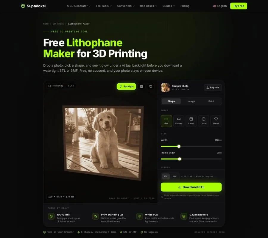
The Lithophane Maker preview shows how a photo reads with light behind the printed panel.
If you are planning a layered, multicolor picture rather than a single-color raised tile, the HueForge alternative guide separates filament painting from reliefs and backlit prints. A manual filament change can add contrast to a heightmap, but it does not turn that heightmap into a filament painting.
Terrain tiles can also serve as scenery beside buildings. For that separate task, SupaVoxel’s guide to 3D architecture models explains building-image concept meshes and their limits: they are not dimensioned CAD or BIM models. Keep any required scale under your own control rather than treating an image-derived building as measured geometry.
FAQ
Is white high or low in a heightmap?
White is high by default. Black stays at the top of the base, and lighter grays rise toward the full relief height. Use Invert if the source follows the opposite convention.
Can I make a round terrain tile?
Yes. Select Circle on Shape, then position the image crop. The converter crops it square and trims both the relief and its base to a circle.
Does a heightmap relief need supports?
No. Exported reliefs sit flat on a solid base, with the surface rising from it. Print the base against the bed and use side lighting afterward to show the contours.